TinkerBench is reader-supported. When you buy through links on our site, we may earn an affiliate commission.
How to Read Electronic Schematics: A Beginner’s Tutorial
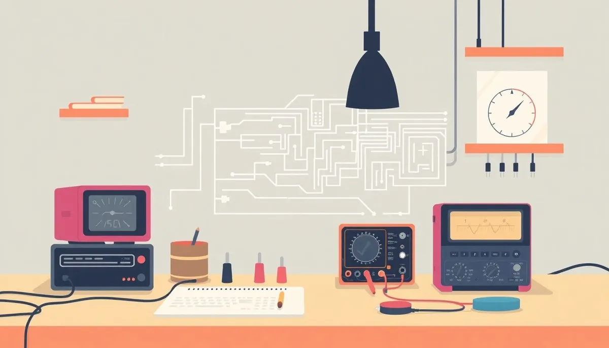
Electronic schematics are the blueprints of the electronics world. They’re abstract diagrams that represent the components in a circuit and how they’re connected. If you want to design your own circuits, troubleshoot existing ones, or even just understand how that cool gadget works, learning to read electronic schematics is an essential skill. This guide will break down the fundamentals, using clear explanations and practical examples, so even a complete beginner can start deciphering these diagrams.
Understanding Basic Components and Symbols
Phone cases · Sponsored
Phone Cases For All — 50,000+ designs. 15% off code FIRST15ALL
The first step to reading schematics is recognizing the symbols that represent different electronic components. Each component has a standardized symbol, although slight variations can exist. Here are some of the most common components and their schematic symbols:
- Resistor: Represented by a zigzag line (older style) or a rectangle (newer, international style). Resistors limit the flow of current.
- Capacitor: Two parallel lines. Capacitors store electrical energy. Polarized capacitors (electrolytic or tantalum) have a ”+” sign to indicate polarity.
- Inductor: A series of curved lines resembling a coil of wire. Inductors store energy in a magnetic field.
- Diode: A triangle pointing to a vertical line. Diodes allow current to flow in only one direction. LEDs (Light Emitting Diodes) have arrows pointing away from the symbol, indicating light emission.
- Transistor: Several types exist, including BJTs (Bipolar Junction Transistors) and FETs (Field-Effect Transistors). Each has its own distinct symbol, but they all function as electronic switches or amplifiers.
- Integrated Circuit (IC): Usually represented by a rectangle with labeled pins. These are complex components containing many individual circuits.
- Voltage Source (Battery/Power Supply): One long line and one short line, often with ”+” and ”-” signs indicating polarity.
- Ground: Several symbols exist, but the most common is three horizontal lines decreasing in length. This represents the reference point for 0 volts.
- Switch: A broken line showing a connection that can be opened or closed.
- Jumper or Connector: Often depicted as a small square or circle.
It’s important to familiarize yourself with these symbols. You can find comprehensive symbol charts online or in electronics textbooks. Don’t feel like you need to memorize them all at once. Start with the basics and learn more as you encounter them in different schematics. Knowing your components will save you from shorting out your new $30 soldering station before you’ve even turned it on.
Reading Resistor Values
Resistors have color bands that indicate their resistance value. While some digital multimeters can measure resistance, knowing how to read the color code is a useful skill. The most common color code uses four bands:
- First band: First digit of the resistance value.
- Second band: Second digit of the resistance value.
- Third band: Multiplier (power of 10 to multiply the first two digits by).
- Fourth band: Tolerance (accuracy of the resistor value).
Each color represents a number:
- Black: 0
- Brown: 1
- Red: 2
- Orange: 3
- Yellow: 4
- Green: 5
- Blue: 6
- Violet: 7
- Gray: 8
- White: 9
For example, a resistor with bands of Brown, Black, Red, and Gold would be 1, 0, multiplied by 10^2 (100), with a 5% tolerance. So, the resistance would be 10 * 100 = 1000 ohms (1 kΩ), with a tolerance of ±5%.
Tracing Circuit Connections and Signal Flow
Schematics use lines to represent wires or conductive paths. These lines show how components are connected to each other. Key things to remember:
- Connections: Where lines intersect, components are electrically connected. A dot at the intersection confirms the connection. If lines cross without a dot, they are not connected.
- Power Rails: Schematics often have dedicated lines for positive voltage (VCC or VDD) and ground (GND). These lines supply power to the circuit. Look for components connected to these rails.
- Signal Flow: Generally, schematics are drawn with the input signal on the left and the output signal on the right. While not a strict rule, it’s a helpful convention to keep in mind. Follow the lines to trace the path of the signal through the different components.
To practice tracing, start with simple circuits. Find a schematic for an LED connected to a battery through a resistor. Identify the positive and negative terminals of the battery, the resistor symbol, and the LED symbol. Trace the path from the positive terminal, through the resistor, through the LED, and back to the negative terminal. This exercise reinforces the fundamental concepts of circuit connections.
Using a Multimeter to Verify Connections
While a schematic shows the intended connections, it’s always good practice to verify the actual connections in a physical circuit, especially when troubleshooting. A multimeter in continuity mode is your best friend here.
- Power Off: Ensure the circuit is completely powered off before testing.
- Continuity Mode: Set your multimeter to continuity mode (usually indicated by a diode symbol or a sound wave symbol).
- Test Points: Place the multimeter probes on the points you wish to test for continuity. If there is a continuous connection (low resistance), the multimeter will beep.
- Verify Connections: Check that the connections match the schematic. If the multimeter doesn’t beep where it should, there’s a break in the connection.
This is particularly useful when working with breadboards, where wires can sometimes come loose. For serious troubleshooting, consider a bench multimeter with good accuracy, but even a cheap handheld multimeter can be surprisingly useful for basic continuity checks.
Understanding Common Circuit Blocks
Phone cases · Sponsored
Phone Cases For All — 50,000+ designs. 15% off code FIRST15ALL
As you gain experience, you’ll start to recognize common circuit blocks that appear repeatedly in different schematics. These blocks perform specific functions, and understanding them will make it easier to grasp the overall operation of a circuit.
- Voltage Dividers: Two resistors in series connected between a voltage source and ground. The voltage at the midpoint is proportional to the ratio of the resistors.
- Operational Amplifiers (Op-Amps): Versatile components used for amplification, filtering, and other signal processing tasks. Look for the triangle symbol with ”+” and ”-” inputs.
- Filters: Combinations of resistors, capacitors, and inductors designed to pass certain frequencies while blocking others. Common types include low-pass, high-pass, band-pass, and band-stop filters.
- Oscillators: Circuits that generate a periodic signal, such as a square wave or sine wave.
- Microcontroller Circuits: Often include a microcontroller (like an /products/b008grtsv6-arduino-uno-rev3-a000066-atmega328p-microcontroller-16mhz-14/Check on Amazon →), associated components like crystals and decoupling capacitors, and input/output connections.
Learning to identify these blocks will allow you to analyze schematics more efficiently. Instead of focusing on individual components, you can understand the function of each block and how they interact with each other.
Reading Semiconductor Pinouts
Semiconductor devices like transistors, diodes, and integrated circuits have multiple pins that need to be connected correctly for the circuit to function. The datasheet for each component specifies the pinout, which is a diagram showing the function of each pin.
- Find the Datasheet: The first step is to find the datasheet for the component. You can usually find it by searching the component’s part number online (e.g., “LM358 datasheet”).
- Locate the Pinout Diagram: The datasheet will contain a pinout diagram, which shows the pin numbers and their corresponding functions (e.g., “VCC,” “GND,” “Input,” “Output”).
- Orientation: Pay attention to the orientation of the pinout diagram. Some diagrams show the component viewed from the top, while others show it from the bottom. Usually, there’s a notch, dot, or other marking on the physical component to indicate pin 1.
- Double-Check: Always double-check the pinout before connecting the component to your circuit. Connecting a pin to the wrong voltage can destroy the component.
Practice and Resources
The best way to learn to read electronic schematics is to practice. Start with simple schematics and gradually work your way up to more complex ones. Here are some resources that can help:
- Online Tutorials: Numerous websites and YouTube channels offer tutorials on electronics and schematics.
- Books: Books on basic electronics often include chapters on reading schematics.
- Electronics Kits: Building electronics kits is a great way to learn by doing. The kits typically come with schematics and instructions.
- Online Forums: Electronics forums are a great place to ask questions and get help from experienced hobbyists.
Don’t be afraid to make mistakes. Everyone makes mistakes when they’re learning. The important thing is to learn from your mistakes and keep practicing. And if you find yourself struggling with a specific concept, don’t hesitate to ask for help. The electronics community is generally very supportive of beginners.
Reading schematics is a skill that takes time and practice to develop. But with patience and persistence, you can master this essential skill and unlock a world of possibilities in electronics.